| >> Differential
speed regulation
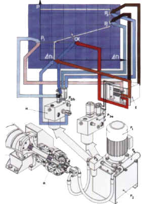
>>> General There are two basic regulation models, digital and analog. The digital regulation permits a hand adjustable, fixed differential speed, which will 'boost' the differential speed to the maximum at some variable preset pressure (scroll torque). The analog regulation permits a hand adjustable fixed differential speed (so-called base speed delta n), and a gradual increase in differential speed as pressure (scroll torque) increases. The point at witch the differential speed increases, called the regulation point (P1) is variable, and the rate of increase (a) is also adjustable. Table IV shows the analog regulation. With both analog and digital regulation, safety cut-outs are provided in the case of high torque (P2) and very high torque (P3). These are signaled by pressure switches (adjustable) and are usually set-up to cut out the feed pump at (P2) and cut-off the bowl drive ant (P3). A pressure relief valve protects the system from overload, preventing damage to the scroll drive by over torque. This is at a higher value than P3, and has the effect of maintaining maximum torque on the scroll so that, as the bowl runs down in speed, the falling 'G' forces will often allow the scroll to commence rotation again and 'unplug' a blocked machine. Note: >>> Hydrostatic regulation systems A specific control block can be mounted on the tank top, according to the required mode. The hydrostatically regulated control block (P3H) uses the direct feedback of variable pressure i.e. variable scroll torque. The regulation characteristic are adjustable through three hydrostatic valves (see table IV), the emergency functions are set on a manometer pressure gauge and switch. Such systems are advantageous for their easy operation and reliability. >>> Electronic regulation systems
The three regulation parameters are easily adjustable through
potentiometers on the electronic unit (E).
If a CVC unit is used, then the following additional advantages are:
|