| >> Rotodiff
>>> Components
>>> The hydraulic scroll drive motor ROTODIFF >>>> General:
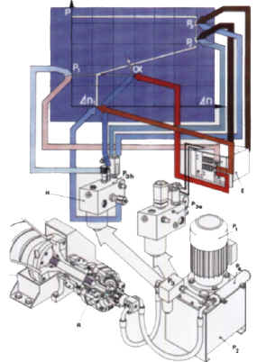
>>>> Working principal of the hydraulic motor The hydraulic motor is a positive displacement radial piston motor. The cam (R4) transmits the force exerted by the piston rollers (R8) through pressure from the pistons (R7). The tangential component of this force produces the rotation of the rotor (R6). The pistons in the cylinder are subject to fluid under pressure via the distributor (R5) which is mechanically linked to the cam. The cylinders are thus alternately connected to the high pressure of the hydraulic feed system (working stroke; red path) and the low pressure of the casing (return stroke; blue path). >>>> Working principal of the transfer seal This element is critical for the function of the hydraulic motor.
It has the ensure a very low leakage rate under highest pressures,
and must have a adequate passage for the high pressure oil flow
as well as extremely low friction loss. A ball cone (R9) is placed
on the rotating part eccentrically, and is connected via a double
cone floating eccentric ring (R10) to the stationary, compensation
cap (R11). The rotating ball cone and stationary compensation cap
(parts R9 + R11) cause a tumbling motion of the floating eccentric
ring, which continually laps and polishes the contracting surfaces.
A considerable axial force is generated between the stationary and
the rotating part. This axial force is contained by the two angular
ball bearings (R12).
|